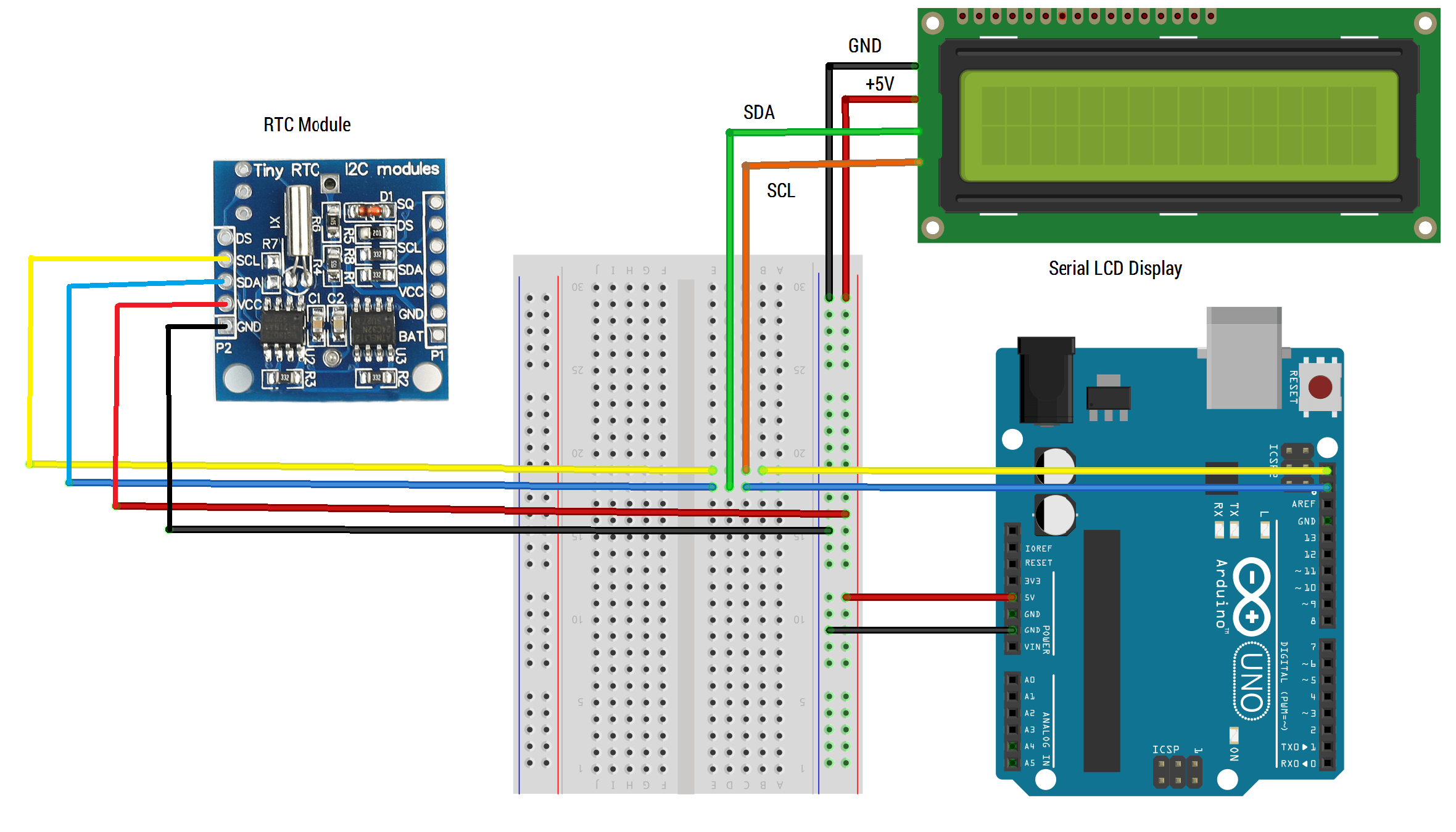

To simplify communication between Arduino IDE and LCD module, we need to download LiquidCrystal library to make use of a built program in Arduino.

So, it will have 16×2 32 characters in total and each character will be made of 5×8 Pixel. There are a lot of combinations available like 8×1, 8×2, 10×2, 16×1, etc. Pin 16 (CATHODE/LEDK/-ve pin of the LED): This pin is connected to GND. 16×2 LCD is named so because it has 16 Columns and 2 Rows. MCP2515 Library for using CAN Communication and LiquidCrsytal Library for using 16x2 LCD with Arduino. Pin15 (ANODE/LEDA/+ve pin of the LED): This pin is connected to +5V (DHT11) sensor data from Arduino Nano to Arduino Uno via CAN bus module MCP2515. For example, MISO on Nano’s ICSP header is connected to MISO / digital pin 12. In 4-wire mode, only four pins are connected to the microcontroller unit like 0 to 3, whereas in 8-wire mode, 8-pins are connected to microcontroller unit like 0 to 7. The Arduino Nano, as the name suggests is a compact, complete and bread-board friendly microcontroller board. These pins are connected in two-wire modes like 4-wire mode and 8-wire mode. Pins 7-14 (Data Pins/D0……D7): These pins are used to send data to the display. Pin 6 (Enable(E)): This pin should be held high to execute Read/Write process, and it is connected to the microcontroller unit & constantly held high. Pin5 (Read/Write(RW)): This pin toggles the display among the read or writes operation, and it is connected to a microcontroller unit pin to get either 0 or 1 (0 = Write Operation, and 1 = Read Operation). Pin4 (RS/Register Select/Control Pin): This pin toggles among command or data register, used to connect a microcontroller unit pin and obtains either 0 or 1(0 = data mode, and 1 = command mode). Pin3 (V0/VEE/Control Pin): This pin regulates the difference of the display, used to connect a changeable POT that can supply 0 to 5V. Pin2 (VCC/VDD/Source Pin): This is the voltage supply pin of the display, used to connect the supply pin of the power source. Pin1 (VSS/Ground): This is a GND pin of display, used to connect the GND terminal of the microcontroller unit or power source. Now in the 14 pins there are 8 data pins (7-14 or D0-D7), 2 power supply pins (1&2 or VSS&VDD or GND&+5v), 3rd pin for contrast control (VEE-controls how thick the characters should be shown), and 3 control pins (RS&RW&E). One can power or leave the back light pins. In 16×2 LCD there are 16 pins over all if there is a back light, if there is no back light there will be 14 pins. Working with both 8-bit and 4-bit mode.

Each character is built by a 5×8-pixel dots.Consists of two rows and each row print 16 characters.Alphanumeric LCD display (alphabets, number, special characters).


 0 kommentar(er)
